Electrical Review, December 8, 1905, pages 849-852:
The Murgas System of
Wireless Telegraphy.
_______________________
By Joseph
Murgas.THIS invention relates to
means for transmitting intelligence through disturbances in the ether and
dispensing with wires. The art to which the invention belongs is commonly
designated as wireless telegraphy.
In
patents Nos. 759,825 and 759,826, granted to me May 10, 1904, a method and means
are set forth whereby messages may be transmitted with greater rapidity than
previously obtainable. According to the system therein described, tones of
different pitch are employed in place of the dot and dash of the well-known
Morse system. This is accomplished by causing different spark-gap frequencies at
the sending station corresponding to the different tones, and these frequencies
are produced by a plurality of interrupters, any one of which may be included at
will in the circuit of a source of direct current. This means of producing
sparks of the desired frequencies has disadvantages ; among which may be
mentioned those which are well known to be attendant upon the rupture of an
electric circuit, such as arcing at the interrupter terminals and consequent
destruction of these terminals, especially where large amounts of energy are
employed, as well as the disadvantages attendant upon moving parts.
It is the main object of the present invention to
produce different spark frequencies from a source of current without the
employment of interrupters.
Auxiliary and other
objects of the invention will appear hereinafter. 
In
the accompanying drawings, which illustrate the invention,
Fig. 1 is a diagram showing the apparatus of one
station and the connection thereof.
Fig. 2 is a
detail of an improved imperfect contact, and
Fig. 3
is a diagram showing an improved arrangement of receiving apparatus.
The transmission of a message presupposes the
existence of two stations, one sending and the other receiving, but as the
apparatus at two stations is identical, an illustration of the apparatus at one
is sufficient for the purposes of description.
Referring to Fig. 1, a station comprises sending
apparatus A, receiving apparatus B, the usual antennæ or aerial wire C, and
switching means D, for connecting either the sending or the receiving apparatus
to the antennæ at will.
The sending apparatus
comprises a source 1 of alternating current, one terminal of which is connected
to a terminal of the primary of the transformer 2. The other terminal of the
primary is connected to one end of an inductance 3, and also to one terminal of
a normally open switch or key 4, the other terminal of the switch being
connected to the other terminal of the alternating-current source. Other keys,
5, 6 and 7, similar to the key 4, are also connected to the last-mentioned
terminal of the source 1, and to taps taken from different points of the
inductance 3, so that by closing the proper key the source may be connected
directly to the terminals of the transformer primary, or any one of several
portions of the inductance may be connected in circuit therewith. 
A spark-gap 8 is connected across the secondary of
the transformer. The gap, as a whole, may consist of a plurality of breaks as
shown or may consist of but a single break. The terminals of the gap are
preferably made adjustable, as shown. The terminals of the gap are respectively
connected through the condensers 9 and 10, with the contacts 11 and 12 of the
switch D. The switch D may be of the well-known three-pole double-throw type.
The middle contacts 13, 14 and 15 of the switch are, in the order named,
connected one to one end of the inductance 16, and to the earth at 17, another
to the sliding contact 18, adapted to contact with the coils of the inductance
16, and the other to the other end of the inductance 16 and to the antennæ C. It
will now be seen that when the switch D is thrown downwardly, the transformer
secondary and spark-gap connected in parallel are connected through condensers
in shunt with an inductance interposed between the antennæ and ground. The
amount of the inductance included between the terminals of the secondary circuit
may be regulated by sliding the contact 18 in one direction or the other as may
be required to include a greater or less number of turns. To effect a further
and nicer adjustment of the inductance, means may be provided for varying the
distances between its turns. This may be accomplished by means of a plunger 19,
bearing against the end of the inductance coil and moved in one direction or the
other by a suitably mounted screw 20. When the screw is turned in one direction
the coil will be compressed, while when the screw is turned in the other
direction the coil will be lengthened.
The apparatus
of the secondary circuit described, containing the secondary of the transformer,
the spark-gap, the condensers and the inductance, constitutes an oscillatory
circuit well known in the art, and which may be adjusted in a well-known manner
to produce the desired results. 
When
messages are to be sent by means of tones, as set forth in the patents before
referred to, the alternator is adjusted to run at a suitable frequency, which
may be fixed. The spark frequency depends upon the length of the gap, being less
when the spark-gap is greater, and vice versa, and the gap is adjusted so that
when the key 4 is closed (the alternator connected direct across the transformer
primary) a spark frequency corresponding to the frequency of the alternator and
a tone is produced. It will be understood that the inductance capacity and
resistance of the oscillator will be adjusted in a well-known manner to produce
the desired oscillatory effects. To secure another tone, the spark frequency may
be lowered by inserting inductance in the primary circuit. This may be
accomplished by depressing the key 5, which is connected to a point in the
inductance 3 such that sufficient inductance will be included in the primary
circuit to produce a spark frequency corresponding to a lower tone. This tone
will differ by an octave or octaves from the first, and the point at which the
key is to be connected, to include the proper amount of inductance, may be
ascertained by gradually inserting inductance until the tone is produced. The
keys 4 and 5 and connected apparatus are sufficient for the purposes of sending
a message, since two tones will fulfil that purpose, but if other tones are
desired, additional keys, as 6 and 7, can be connected to other points of the
inductance 3, corresponding respectively to other tones. The points at which the
additional keys are to be connected may be ascertained as before described, and
the several tones will differ from each other by an octave or octaves. It will
now be obvious that a message is sent by depressing the keys in the proper order
to produce tones as required by the code employed.
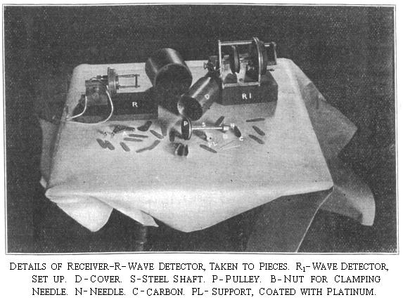
The receiving apparatus comprises an imperfect
contact driven by the motor 21. As in my patent referred to, and the contact
itself may be as therein described, but is here shown as a number of carbon bars
22, bearing at one end upon a polished steel shaft 23, driven by the motor, and
at the other end upon a platinum support 43. As shown in Fig. 2, each of the
carbon bars 22 is provided with a hole 44 at one end, through which the shaft 23
passes, while the other end of each bar rests freely upon the platinum support.
While the apparatus shown in Fig. 1, a simple, imperfect contact, is employed,
superior results are obtained by the employment of a plurality of them. The
manner of employing a plurality of contacts is illustrated in Fig. 3. Referring
to this figure, the shaft 23 is connected to a driving motor by any suitable
means, as a belt 45. Bearing upon this shaft and upon platinum supports 43A and 43C, as before described, are two sets
of carbon bars 22A and 22C. The
antennæ are electrically connected to the shaft and each of the platinum
supports is connected through a condenser to the ground. Message-receiving
means, which may consist of a telephone-receiver 37 and a battery 38, are
connected in series between the platinum supports. It will be observed that in
this arrangement the imperfect contacts are connected in parallel between the
antennæ and ground, and that they are connected in series across the
message-receiving means. 
The
terminals of the contact are connected to the upper terminals 24 and 25 of the
switch D, and when that switch is thrown upwardly these terminals are connected
respectively to the antennæ and ground. A condenser 26 is inserted in one of the
connections. A switch 27 may be provided for disconnecting the imperfect contact
when sending, as strong discharges through the contact have been observed when
oscillating waves are produced in the spark-gap. A switch 28, when bearing upon
one contact 29, connects in calling apparatus, and when upon another contact 30,
connects in receiving apparatus.
The call-receiving
apparatus comprises a bell 31, connected in circuit with a battery 32, and a
switch 33. The movable member of the switch is carried by a movable coil 34,
mounted to turn in the field of magnets 35 and 36. When the switch 28 is upon
the contact 29, the coil 34 is connected across the imperfect contact and upon
receipt of an impulse at the station, the coil 34 is energized and moves in the
magnetic field, thereby closing the circuit through the battery and bell 31,
whereupon the bell rings.
The message-receiving
apparatus comprises a telephone-receiver 37, and a battery 38. When the switch
28 is upon the contact 30, the receiver and battery are connected across the
terminals of the imperfect contact and messages are received, as described in my
patents referred to.
Preferably a switch 39 is
provided which, when engaging contact 40, connects the antennæ to the sending or
receiving apparatus, and when engaging contact 41 disconnects the antennæ from
the apparatus and connects them directly with the ground as at 42. By this means
contact 41 disconnects the antennæ from the station apparatus and connected with
the ground in time of storm or at other times. A rope 46 may be connected with
the switch 39, or other suitable means may be provided whereby the switch may be
operated without rendering it necessary for the operator to place himself in
dangerous proximity thereto.
It is to be understood
that various constructions and arrangements of apparatus may embody the
invention, and it should not, therefore, be limited to the structure and
arrangement shown.